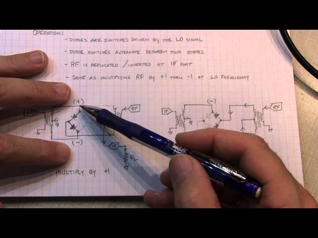
#167: How a Diode Ring Mixer works | Mixer operation theory and measurement
Комментарии:

Even though only one half of the RF transformer is used at a time, do the coils used by the opposing polarity not resist the conducting of current in that direction, since they are all mechanically connected?
Ответить
Question about theory: The diode ring mixer shown here seems very different from the Gilbert Cell mixer described elsewhere. The diode ring seems to “chop” one frequency with another frequency. That doesn’t seem like “multiplication”, but more of a harmonic creation mechanism. The undesired harmonics are eliminated with filtering, but with losses from the energy spent in suppressed harmonics. The Gilbert Cell seems like a true multiplication, where the product of 2 sinusoids is produced accurately, without creating a lot of extraneous harmonics. It is therefore less noisy. Is this a roughly true comparison?
Ответить
What do you need to drive this mixer? How much voltage, and what kind of impedance does it expose to the driver side?
Ответить
This is the best explanation about mixers I found over the YT! Thanks!!!
Ответить
You say that the point between two diode acts as ground. For the transformer (RF side) both ends can be connected directly to ground and no need to connect between two diodes. This should also work isn't? But then how does RF gets multiplied if the LO signal is not affecting the induction of second transfer? I think there will be a back emf from the first transformer and that will allow some charge to flow from point (between two diodes) towards second transformer and affect the induction level at that moment i.e. gets mix with induction generated by RF signal?
Ответить
perfect!
Ответить
nice. correct me if I am wrong but there is gain in the mixer also,...(?)
Ответить
very good explained. Thank you !!!
Ответить
One aspect I have not seen addressed (yet) is drive level. The signal amplitude at the diodes I think should be at least 1.5 v, since 2 x silicon diode voltage drops of 0.7 v would be at least 1.4 volts to turn them on. But I do not know what the transformer ratio is, so I cannot guess at the LO amplitude. I also would like to play with IF filters, but do not know the proper drive level. My initial thought would be to drive a filter (mechanical, crystal, or piezo) with a sig gen at the filter's center frequency, slowly increasing the amplitude until I see some saturation evidenced by output ceasing to increase. At some point, I would expect damage from excessive drive, so I would like to stay below that. Radiofun232 comes close to addressing this with some of his lash-ups, but my questions remain unanswered.
Ответить
Why do you call this mixer a Multiplier when you getting the Sum and the Difference?
Ответить
I find mixers interesting. I realize that this is an entry-level, rudimentary mixer, but...
Could this general type of mixer be biased into either the positive or negative, (and then capacitively/AC coupled) to reduce the crossover distortion causing the odd harmonics?
This is a good video, as most of yours are. Thank you. (Generally, I have been so impressed by Amateur radio licensees/operators knowledge of RF electronics that it prompted me to get my General.)

Very interesting video Alan !! I noticed that my IFR-1000S has similar circuits that seem to mimic your Diode Ring Mixer video !! 73's Gary Grove
Ответить
Thanks so much. I came here from your other mixer video. I've got a good handle on this now, at least for this type of mixer. I'm more of a digital domain, embedded guy but am getting the urge to try some RF projects.
Ответить
I was wondering if I used a full bridge rectifier package with 4 pins... would that work?
Ответить
Question: I've built a diode mixer for AM modulation and compared it with the Gilbert Cell modulator. Does the diode version always suppress the carrier? or can it be adjusted produce a traditional AM signal like the Gilbert Cell?
Ответить
awesome and subscribed
Ответить
You explained very well how the LO changes the polarity of the IF output, but there is a more complicated interaction of that polarity change on the RF input which is changing at a different rate than LO (if the frequencies of LO and RF are different), that is when the IF output becomes the sum and difference of the LO and RF frequencies. Am I correct or am I in the dark corner???
Ответить
Another perfect video. It would be nice to talk a little about the transformer. How the number of turns was found? Any math involved or just trial and error? Thank you!
Ответить
I'd like to point out that the various GROUND connections associated with the transformers and signal inputs/outputs are rather critical. Sad that most communications textbooks do not highlight the necessity of correct ground connections in order for the mixer, whether used as a DSB-SC modulator or a product detector, to operate as expected. Thanks so much for including them in your carefully drawn hand sketches.
Ответить
Is the first transformer's only purpose creating the phase split?
Ответить
Hi Alan. You comment that the IF output should have a good termination / a nice broad band termination, to prevent reflections. I’m all good with that. There is plenty of similar discussion on the web etc that agrees but “everyone” talks about a 50R IF termination. Is there something special about 50R or is it just a convention? Reading the comments I see the transformers XL need to be 4 or 5 times greater than RL … maybe 50R IF translates to a “practical” number of windings for homebrew transformers? Further, I assume the more XL the more attenuation on the ports, desensitising the mixer?? Thank you for letting me think out loud as I don’t have any Elmers etc to discuss with.
Ответить
Hi Alan. Im TA9AAP from Turkey. I hope you will answer my question. There are many different types of diode ring mixer circuits in professional devices and in many schemes. I have been working for a long time to make a handmade QRP device. But I have seen some diode mixer schemes with 4 diodes, one transformer and one potentiometer (LO). I couldn't find anything when I searched about the number of turns of these, what the value of the potentiometer used should be and how I should adapt the impedance. Yes, it is a simple diode mixer, but I want to design a single transformer that is not trifiliar or bifiliar, but a mixer with 4 diodes and only one potentiometer. Can you please help me on how to do it?
Ответить
Hi , Thank you very much for the nice video and your information, but I was confused and about the value of coil , you made mixer with 10 turns of the coil with core T37-6 , and the other with 10 turns FT37-43 , which are very different in T37-6 =0.3 UH FT37-43= 35 UH the value of coils in the mixer It has no effect ? I am also happy if you have MCL SBL-1 mixer , measure the values of bases 1 and 2 or 7and 8 thank you in advance .
Ответить
Great.. sir please make a video on working of bfo. Also a video on total working of bitx20 by OM ashar farhan with tx and rx procedure. Thank you.
Ответить
Howdy.
Mesmerizing ...
Regards.

please explain and make little circuit of how Tuning Meter Led indicator circuit works in old Radio ?
Ответить
The diodes are not acting as switches to accomplish modulating...that's a different type of circuit.
The diodes are non linear elements. That accomplishes the mixing.
A switch only has two states so it can't mx from just that...

Thanks for clearing concepts. Can you please say is any low frequency (kHz) QPSK modulator available or not?
Ответить
The explanation on the diode circuit diagram is amazing and in-depth. Classroom courses pale in comparison.
Ответить
It is RF black magic! TU FER this !!
Ответить
Thank you for nice explanation
Ответить
The diagram on the right has two IFs, the one on the left does not. I assume the IF near the center of the page on the right diagram should be labeled LO.
Ответить
For Bridge Rectifiers if rating is 30 amps that means 30amps divided by 4 diodes in the bridge rectifier = 7.5amps per diode? Is this the same for a Diode Ring Mixer in RF circuits that the RF Mixer current rating is divided by 4 to the RF input power?
Ответить
A confusing point about explaining the mixer is the multiplication part.
The actual process is Superposition of two voltages each one fluctuating at a different frequency. If you were to plot several cycles of each signal (the RF and the LO), one a above the other on graph paper, with seconds on the X axis and voltage on the Y axis, a 3rd waveform can be drawn, the beat frequency, as the summing of the voltages of the two waves.
For example, at time T = 7 seconds, say, freq #1 is at 7 volts, freq #2 is at -3 volts, adding you have 7 + (-3) = 7 - 3 = 4 volts, and you'd plot that on the graph paper just below the two source frequencies (RF and LO). Then repeat at 1 second intervals, adding the voltages at each second.
The resulting waveform will be the beat frequency. Constructive interference occurs when both input waves are swinging positive voltage above the zero reference line. Destructive interference occurs when one of the input waves is below the line, and the resulting amplitude is reduced by the negative-swinging input wave.
So when someone points out "it's not multiplication, it is Superposition. Nature does not multiply superposed waves, it adds them" you then (and only then) have to say "if you look at the trig functions, you start with a multiplication."
My preference is to start by saying 'we have two frequencies, they'll be brought together and the result will be a wave that is the superposition of the two input frequencies, but here's the math"
Otherwise, having an assignment to familiarize students with how the beat frequency is created from the two input waves - by plotting the 2 waves then adding - confuses them. "Why are we adding? Shouldn't we be multiplying?"
No, there's a difference between how the circuit combines the voltages of the two frequencies, and how the math abstracts that process.
Also, "where does the new frequency come from?"
Answer - it is the repeating pattern of how the Constructive Interference and Destructive Interference behave from adding the waves.
.

Thank you for great explanation.
Ответить
Hi Alan, would 32 AWG also be ok? T37 is really small. Maybe 30 AWG is good for bigger toroid diameters too, so I can only buy one coil to suit all.
Ответить
i do not understand something, is the carrier supressed?
Ответить
Thanks for the explanations! There are so much specific details in RF electronics..
Ответить
Fantastic video, thank you! Literally almost all the information on the internet is calling a 4 quadrant multiplier a ring modulator (It's not!!). This is the only video I've seen that gets it right.
Ответить
👍
Ответить
wow Alan, that was awesome. I knew how mixing worked, but to see the ways you did this it really made me think.. Also -- that was really cool to see a custom math expression on a scope, I've never seen custom expressions before, only built-in
Ответить
Man, can I just say you are one hell of a good explainer of RF stuff
Ответить
Very interesting.. its like you have a rectifier switched by the RF?
Ответить
Where did you get your inductors from? Do you have a part number? If hand-made, what is the gauge of wire and numbers of turns?
Ответить


