555 Timer Modes Explained - The Learning Circuit
Комментарии:

Am I right that a 555 timer technically contains an SR latch, not an SR flip-flop? A flip-flop is edge-triggered meaning the inputs take effect only when a clock input goes low->high or high->low. A latch is level-triggered so the output changes whenever the inputs change level and doesn't need a clock. Since the 555 timer doesn't take a clock signal, I think it contains an SR latch not an SR flip-flop.
Ответить
You are amazing, girlie ♥️
Thanks!

Please which pin can be used for output of 555ic than pin 3?
Ответить
Would you please explain in brief about pin 5 of the ne555 timer ic.
Ответить
it was the "arduino" of an entire generation of makers
Ответить
Could you explain the IR2110 ic
Ответить
Very interesting, you are good ❤
Ответить
Thank you
Ответить
glad to attend this class . thanks !
Ответить
Nice info, thanks :)
Ответить
Everytime she says flipflop it feels im watching multidimensional cable from rick and morty
Ответить
You can easily make this video much more interesting.
Create a vibrator using the 555 and bring yourself to orgasm.,!

Perfect discussion, many thanks for the valuable information with simple explanation
Ответить
Time travel?
Ответить
Little bit confuse. PNP of pin4.
Positive from abundant supply and Positive from capacitor will capacitor discharge ?🤔

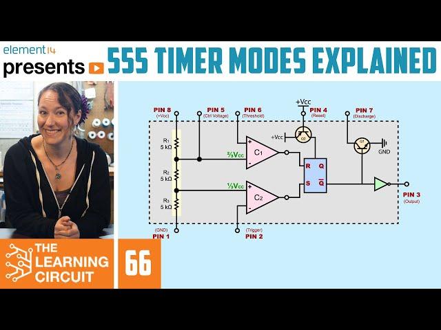
I believe your Q2 logic is incorrect, the circuit is correctly drawn, Q2 would turn on with a low voltage (Gnd) on base and turn off with a high voltage (Vcc). looking at the bigger circuit, the positive voltage supplied from Q2 collector is the reset to the RS flip flop.
Ответить
Hi am trying to use a 555 to make and inverter for low side and high side but I can’t get it to inverter two signal and when I use a bjt to inverter the signal I get the same high side signal turning on the mosfet at the same time , I see a lot of circuit showing a bjt and it inverter the signal to two high and low but i the same circuit and all design end up with the same results the two mosfet turn on the same time
Ответить
First time ever being taught light current electronics by a female. Why no more girls into electronics. It's wierd. Its not for one gender, its got 2 polaritys,
Ответить
I understand all what's said because I know how a 555 works, not sure if I can put myself in a noob's shoes 🤔 genuinely curioushow clear is the explanation to noobs with the prerequisites of voltage divider and rc circuit. again for most who know, I guess it's greately explained!
Ответить
قناة محترمه
Ответить
Another excellent video Karen. I can never get enough of this IC. Most videos say, oh here it circuit for flashing an LED, have a good day. There was missing a little bit about how the resistor values in BISTABLE mode control both the charging rate and the discharging rate and can be calculated to determine the duty cycle. Otherwise, spot on!
Ответить
Why does pressing the button stop current flowing into pin 2. Wouldn't it just make it flow to both ground AND pin 2?
Ответить
I really appreciate this explanation, but I think I'm missing something about how the reset pin (pin 4) works. Since it's connected to the base of a PNP transistor, doesn't that mean that when pin 4 is set to low it will allow the Vcc current into the flipflop and set Q to LOW. From how I'm understanding your explanation, you are considering this transistor to be NPN. Let me know if I'm misinterpreting though!
Ответить
you could swear you were watching a Plumbus commercial
Ответить
Please include timestamps and name of 3 modes in title of video it dosent come in search sometimes
Ответить
Still see d104 ....great video btw
Ответить
This and and the other presentation in the series are absolutely fantastic. Thanks !. One thing which was slightly unclear to me in bistable mode starting with low threshold, is why do I need to put trigger high to get high output, if it is high when trigger is low as well (with threshold low). So it seems there is no function for trigger to switch output high (it is high by default). Yes, then, to put output to low, you need to first put trigger low and then threshold high to avoid invalid state. But not to start ? It seems you just need to keep trigger high all the time and play with threshold ?
My use case is when 555 is used as a standby switch to amplifier IC (TDA1554Q). 555 output is directly wired to 'standby' pin of TDA1554Q, which needs it to be around VCC for TDA1554Q to be on.

thanks
Ответить
The 555 was produced by Signetics in 1972. It was a marvel for its time, but many of the same functions can be done with two or three transistors and careful design. The heart of the 555 is a window comparator. Yes, it is an ingenious design.
Ответить
Great video.
Ответить
Very nice presentation! When I was an Engieernig student (mid 70's), I discovered 555 and made lots of timers, for me and my friends. I used them to switch off the radio, after say one hour. I used typical monostable mode. Switching components, they could be programmed for diffenent turn-off periods. After many years, the 555 is still one of the most versatile and useful components in electronics. I had to measure and draw the block diagram, with a hard work. Your video is absolutely fantastic.
Regards!

you speak so fast as if you were talking to a friend. I need to slow down 75% to keep up with what you say. greetings.
Ответить
What is price of 555 processor with pin holder sockets?
Ответить
Does this type of micro processor used in PESA radars?
Ответить
aha! now I get it. you're the first to get me to understand it ;'-) (I've watched both clips
Thanks!)
The schematics were very helpful o/

I have a question (monostable mode), initially in the circuit we push the moveable button closed so that it connects Pin-2 to ground, this makes C2 output HIGH which makes S = HIGH which makes the FF output (not-Q) go LOW, this LOW feeds into the transistor making it OFF which breaks the pathway between the capacitor and the GND associated with Q1 so that lets the capacitor charge. I am all good on that...then the capacitor gets above 2/3 Vcc and this makes C1= HIGH which makes the output of the FF(not-Q) go HIGH which then feeds into the transistor and turns in ON so it's ground can now connect to the capacitor to drain it. I am pretty sure that's correct, however what I don't get is the moveable button during the RESET stage, does the button stay pushed down and connected to GND, or does the button automatically move back up breaking from GND? How does the button move back into it's up position? I hope that question makes sense.
Ответить
Put 6K resistors and make 666 timer :D
Ответить
Thanks ...happy new yr too
Ответить
hi 555 ic voltage deviate how it work and other ic frequency output how it work please
Ответить
The world's best Queen teacher
Ответить
Best video on 555 timer explanation but a little mistake on pnp reset transistor over there as pnp enter saturation region (turns ON) when pulled low and cut-off region (turns OFF) when pulled high ✍🏾
Ответить
Ok, thanks...but I have yet to figure out how, when Set is High and output therefore is high...where is the full-voltage output coming from to power whatever it is that you want powered? What am I missing here?
Cheers

u r awesome.....huge respect from india
Ответить
Thank you
Ответить
This video is sooooooo good compared to the others with same topic! I wish I could give multiple thumb-ups 👍🏻👍🏻👍🏻👍🏻👍🏻👍🏻👍🏻👍🏻👍🏻👍🏻
Ответить
Animated schematics are great and can be more great
Ответить
Very nice explaination . Very very Thanks.
Ответить


