Комментарии:

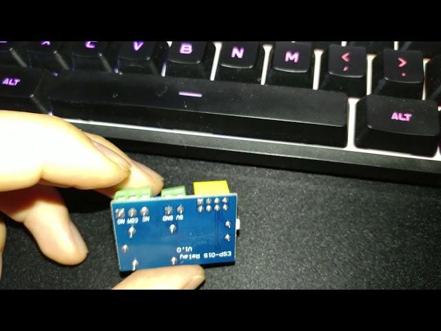
i need pic of your modification module, i need some help with this relay module
Ответить
Excuse me, does this module normally works with ESP-01S without any patches ? i noticed that some difference in pinouts between ESP-01 and ESP-01S. It seems easiest way put into trash all ESP-01 and purchase ESP-01S and don’t f*** the brain.
Ответить
..after so long keeping it not knowing what was wrong..today I fixed it according to your advice.. 1 - jump en to vcc 2. Remove R2 202 resistor...it finally worked tq mate..used switched USB programmer for esp-01s sketch upload..
Ответить
Just checked...in my module IOTMCU V4.0 ...found CH_PD is not connected to anything..Thanks bor...although it works good with blynk but giving problem using esphome....I hope fixing ch_pd high will fix my problem...will update soon
Ответить
Thanks man! And I thought I was doing something wrong..
Ответить
Buy rele v.4 and enjoy!
Ответить
As You can see on the film, this module is dedicated for ESP-01S, but not ESP-01.
With ESP-01S it works fine. But if You have only ESP-01 You must follow the advice from this film.

Thanks a lot :)
Ответить
Thank you so much !!!!! I wasted precious time wondering what the issue was, until I stumbled on you video . All works now. You get to wonder how they do their QA when building these products. ;-)
Ответить
Super ! Thank you for this great tip, you saved my day., interestingly I have the Relay PCB version 4.0 and I had to short the pins to get it working, removal resistor was not needed.
Ответить
Thanks - this really works - I appreciate your posting it.
Ответить
thanks, that relays doesnt do the only thing that they were built in to do
Ответить
sorry for comment an old video , but i have the almost the same module but with 2 relays and I've tried to do the same thing but it doesn't work , do you know the fix of this module?
Ответить
Thanks for the information, I have a device ESP-01 relay v1.0, with R1(103=10K), R2(202=2K), I just removed R2 it all is working fine.
Ответить
Goddamit, THANKYOU for this, I've been pulling my hair out (and there isn't much as it is) just to get it booting, but it won't pull the relay?
Ответить
I think it was made to use their ap, not designed to be reprogrammed
Ответить
Thank you for this. I bought a few of these and I'd completely failed to get them to work. Desoldering the 10k R2 (i.e. the resistor closest to the edge of the board, and connecting CH_PD to Vcc did the trick. What I don't understand is how this design ever got past testing since it's broken but at least now I know how to fix it.
Ответить
hello tnx for this tutorial . you have been of much help. wich firmwre are you using to connect the esp-01 with alexa?
Ответить
HELP PLEASE!!!
Keep getting this error in the IDE when trying to compile. (exit status 1
Error compiling for board Generic ESP8266 Module.) I choose Generic ESp 8266 module, Any help Please
. My ESP 8266 modules are good
1

Good Job, thank you very much.
I bought about 20 of that relay boards to build some remote valves for my garden watering, because the ESP01 and that relay should work perfect with just a 5V DC supply and WiFi Control.
The CH_EN I found already out myself, but with the resistors is a very hard stuff. Thanks for discovering. I will inform my dealer about that buggy item.

Thank you so much bro. This video is really helpful.!!!!
Ответить
Why do the keep selling it with such issues? Is there a V1.x available. Especially, the missing isolation distance between ground and 230V is not nice...
Ответить
Excellent video. Thanks,
Ответить
Thank you very much! That was the exact info I needed.
Ответить
keeps me given this error (exit status 1
Error compiling for board Generic ESP8266 Module.)... any help? ( I choose Generic ESp 8266 module, the com port is ok... and using IDE of arduino to program)

I do exactly as You say, but still can`t firmware my esp( I remove 10k resistor (in my case R1 and R2 in reverse, so i remove R2 and R1, and solder back R1 just like in your picture), after that i solder 2 contacts EN and 3v3. After that i tried to connect via TTl module to pc and no one ports are avalilabe. PLEAASE HELP! I firmware with ESP Easy Flasher.
Ответить
Thank you very much !!! now everything works , good job !!
Ответить
i got the version of these. it blinks the leds after powering then doesnt show up in my wifi list. and it keeps getting hot.
Ответить
Nice one! I thought I was missing something as the esp-01 worked fine without the relay assembly. Nice catch.
Ответить
Thanks for this video, Strangely my boards look identical to yours in terms of components but the chip enable pin seems to be fine. I removed the resistor you showed and they're now working great.
Ответить
Hi there
After the modification is it normal that the relay switches when booting?
Would love to fix that aswell or maybe I've forgotten something?

It works <3 , thank you.
Ответить
Thank you very much, in my case I just removed R2 it all is working fine.
Ответить
Risolto grazie al tuo video!
Ответить
Thanks for the clear explanation, appreciated it!
Ответить
I would like to see a movie about this relay wlan unit for non tinkerers. That goes like this: 1. Prepare Unit that way. (if you would like to know why watch this movie) . 2. Download this app and upload this code to the wlan unit. (If you want to learn how to modify the code go to this movie. Buy this component to connect via USB to the Wlan unit). 3. Connect to your switch via this app for windows, this app for android etc. Use this settings (If you want to learn more watch this video) . And now enjoy your new wlan switch device.-- I think such a video would attract hundred thousands more viewers not just tinkerers.
Ответить
Awesome. It works exactly as described in video. Many thanks.
Ответить
perfect.. its works..
thank you.. ^_^

Hi , Thanks for clear explanation. My esp boots and works after I remove R2 and connect Chip_enable pin to VCC. My esp which is ESP8266EX works even without pulling Chip_enable up. I can control GPIO0 and build in led with the software. But Relay and board leds are always on no matter GPIO0 High or low. When I connects Gpio0 to gnd board led turns off and relay closes. Do you have any idea what else should be wrong on the board ?
Ответить
I've desoldered the resistors from R1 and r2. But can't solder back the 2k resistor on r1 because it's so tiny. I tried to put an 2k resistor of my own on r1. But then the esp doesn't boot. If I remove the resistor from r1 the esp boots, but i can not click the relay via GPIO0. What should I do?
Ответить
Thanks for share.
Ответить
What document are you looking at that so nicely lays out the details of the ESP8266?
Ответить
I just connect 3,3v to CH-EN and removed R2 resister. Now is it suppose to work with typical ESP2Relay controller app. still my one doesn't work
Ответить
Many thanks
Ответить
Got half way through debugging this when I found your vid. Superb. All my issues sorted. Many thanks
Ответить
Perfect fixed second time when I paid attention to removing the correct resistor. Would probably have scrapped the board without it.
Ответить
Thank you very much for your helpful information! You saved me. Thank you, thank you.
Ответить
Has anyone manage to fix the relay jitter problem on start up?
Ответить


