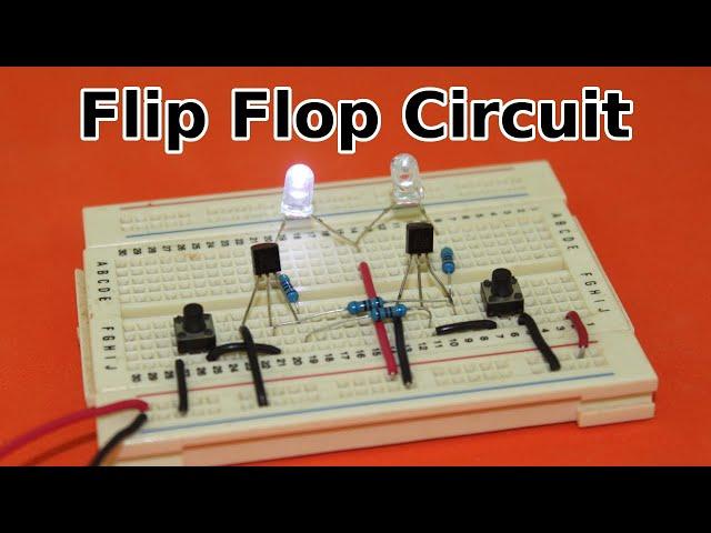
Flip Flop Circuit
Support Ludic Science on Patreon:
https://www.patreon.com/ludicscience
Тэги:
#science #physics #electricity #magnetism #electromagnetism #experiment #homemade #howto #diy #electronics #latchКомментарии:

👍👍👍
Ответить
I is on 0 is off? So the one is on,than you sens that one over to other side than the off is 0?
Ответить
loved the education at the end of the original transistor!
Ответить
What prevents the leds to initially turn on both, won’t the current open both gates simultaneously?
Ответить
Actually you dont need the two base resistors if the collector resistors are big enough to protect the base from too much current.
Ответить
did you used ac power or dc power 12volt?????
Ответить
Good
Ответить
Will you please suggest a circuit to use two 9 watt 220 volt LED bulbs in the flip flop circuit uit
Ответить
bisakah rangkaian ini untuk mengendalikan relay?
Ответить
A really nice explanation! Could you share how you calculated the required resistance values?
Ответить
Çok güzel anlatmışsın kral yaaa çok güzel anlatım çok iyi anladım
Ответить
thanks very much!!
Ответить
If the circuit is on 2, and you put the power off, would it go to 1 when you turn it back on the power/electricity?
Ответить
gonna make a coil gun with this
Ответить
are you using PNP transistors or NPN transistors
Ответить
It's nice, but the circuit is actually a latch. Flip-flops are clocked.
The circuit clearly is not.

Well explained.
Can you explain a situation where if 1 LED (LED1) gets 5V supply (continuously) the 2nd LED (LED2) switches off. But when LED1 does not get a 5V supply the LED2 should switch on. How to do this? Please explain with a circuit diagram.

I first used a 2N2222A116 transistor and the circuit didn't work. But when i used a BC337-40 transistor, it finally worked. Why is that?
Ответить
If we put capicter here it bekm automatic?
Ответить
THANK YOU FOR THIS AMAZING VIDEO
Ответить
What about the small red wire ?!!
Ответить
can you make this with mosfet transistor
Ответить
Tu eres de "Electrónica Practica" a mi no me engañas 😛😁👍
Ответить
Beautifully explained! Thank you very much for this great circuit.
Ответить
pls I'm asking if you can help me with the transistor circuit diagram of an SR latch using two NOR gates
Ответить
Fantastic video, clear and concise, thanks a lot!
Ответить
i'm a 9th grader and i'm watching this for the sake of passing our exams tomorrow (we have a special subject for these engineering and techy stuffs... -.-)
Ответить
Can it be made automatic without the push buttons
Ответить
no eres el de electronica practica paso a paso?
Ответить
I legit have never learned a thing about reading circuit diagrams and that circuit diagram is what helped me understand how this works with real electronics and not just a logic gate simulation. Thanks a ton
Ответить
This is sr latch circuit but u said this is flipflop circuit if u apply trigger then it becomes flipflop please xplain
Ответить
Hi sir request wiring tool direct coil with rpm &frequncy
Ответить
You earned a sub.
Ответить
Great vid.
Ответить
Pretty good explained, Thank you
Ответить
Sir make it 3 phase plz
Ответить
Wow, looking at the circuit it appears to be a symmetrical configuration being the foundation building block. Looks like a astable multivibrator as it lacks capacitors. So when the power turns on and no button pressed yet, which side conducts first?? Would that sided be consistent every time?
Ответить
i feel kinda jealous.
Ответить
i am neither a science student nor a hardware student.
just a programmer who wants to know his computer better...
going down the rabbit hole.

please make a arc lighter and the hand wound high voltage transformer
Ответить
Regarding the ubiquitous Trump comment found in literally every video, no matter how unrelated to politics; Here's my take. This is not the True Trump circuit, as it requires too much user interaction. Also, once a switch has been pressed, the circuit tends to stick with it's "choice", something Trump would obviously never do.
edit:READ MORE CLICK IT DAMMIT
I say, remove the switches, put the center resistors where the switches were, and put some capacitors where the resistors were, and THEN you got yourself a trump circuit.. It flips all the time, based on the relation between the swapped resistors and the capacitance. And it's calle an astable multivibrator, so you can all have your chance to get your joke in now.
Suck it, Guy De Vos.

i prefer the 555 and 556 timers for all my flip flopping needs.
Transistors are cool if the circuit is configured to run on full auto...

Does that mean that for storing a bit, do we have to constantly power it?
Ответить
But how much the speed of the trasistors
Ответить
Like nice video and nice explain 🤔
Ответить
👍👏
Ответить
👌👌👌
Ответить
What if you press down the two buttons at the same time ?
Ответить
thankyou
Ответить
What is the default state when the circuit is powered initially?
Ответить


![[FREE] MAHALIA "LOVE STATION" x ELLA MAI TYPE BEAT |R&B TYPE BEAT 2022 [FREE] MAHALIA "LOVE STATION" x ELLA MAI TYPE BEAT |R&B TYPE BEAT 2022](https://invideo.cc/img/upload/QWZtZTRNNFZiUVk.jpg)


