Комментарии:

Can the resistor 'Re' be equal to zero in this circuit?
Ответить
Thank you for this explanation, how do we define Beta here?
Ответить
As I was hovering looking for a perfect solution .. I just saw your the cover photo and I knew my problem is solved.... And guess what am just 4mins I to the video and I have understood everything... Thanks man .... 🔥🤗
Ответить
If i use exact method even if bre>>10r2 then is it right
Ответить
Thank you
Ответить
Just awesome explanation sir, thank you so much for that video. I have one doubt about beta, how can we take the beta value as constant because in any transistor data sheet the beta value have a range. For example BC548 has a beta range from 110 to 500. So which value should i take while using this transistor for amplification (for a perfect active region). Please explain sir, if possible.
Ответить
bless you sir. Great video
Ответить
Thanks for a very clear and helpful explanation. I now have a much better understanding of how to set up a bias circuit for a BJT, and why a certain amount of "slop" necessarily occurs when calculating actual voltage, current, and resistance values.
Ответить
How are those resistors in parallel? Having a little trouble getting my head around that
Ответить
What is the use of RE in the circuit?how it provide stability?
Ответить
This video helped me understand the biasing of BJT. Thanks a lot sir!
Ответить
Finally someone that made me understand this theory. Thanks a lot.
Ответить
Thanks for the good video. How would you solve the question if there is also a resistor between base of transistor and opposite node? Thanks
Ответить
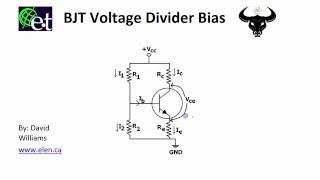
The "short-cut" method calculates the quiescent collector current and dc bias points of a transistor that has infinite β. The stability of the dc bias against changes in β depends purely on the relative size of the emitter resistor Re. That resistor provides negative feedback that stabilises the operating points as well as reducing the distortion of the stage. It comes at the cost of lowering the voltage gain of the stage, which is 3 in this case. It also "absorbs" around 2.5V of the potential output swing.
You can improve the performance of a common emitter by removing some of the negative feedback from the emitter resistance by lowering it, while providing a feedback path from the collector to the base. In other words, derive your base voltage bias (the positive end of R1) from the collector rather than the positive supply rail. Since the emitter resistor only needs to be more than 10 times the dynamic emitter resistance of the transistor (25mV/Ic) to provide reasonable linearity, the emitter can be usefully biased to as little as 250mV above ground, putting the base at about 900mV above ground. If you assume that the collector bias point is around half the supply voltage, you can quickly calculate the ratio of R1 to R2. Knowing the β will allow you to make R1 || R2 less than 1/10 of β.Re for any value of Re. That shows you that the input impedance of the stage is inversely proportional to the collector current, and (all else being equal) you should choose Ic to obtain whatever Zin is required. Somewhere between 1mA and 2mA with a β > 250 or so will result in an input impedance around 5K to 10K.
That solution will allow reasonable gains of around 20 to 30 with good stability and linearity, while maintaining independence of transistor parameters. I recommend it to you.

Thanks so much . Your video has clarified all my doubt. Thanks once more
Ответить
Great BUT why you say voltage divider R1 and R2 and immediately căLculate Rth as parralel ?/
Ответить
The best video i've seen so far, thank you.
Ответить
Excellent explanation. Infinitely more helpful than a university professor
Ответить
Where did you get Re from?
Ответить
Could you please explain how you calculate R(th) as being 8.33 KΩ ?
Ответить
Very useful methode
Ответить
thx a lot bro
Ответить
I find I'm more of a spice warrior then a scientific calculator nerd 😁
Ответить
What is the equation to solve for ro? Anyone
Ответить
Great explanation sir! Now I understand what's going on there
Ответить
Sublime!
Ответить
Thank you for such a crystal clear explanation of a VDB-BJT.
Ответить
Thanks for making this very CLEAR plain English video. I can definitely understand your Canadian English.
Ответить
Only complaint is there is not a download link for a pdf document of this lecture. The information is so good there should be a link.
Ответить
Sir how to get answer uA please tell me i don't uderstands
Ответить
Thank you so much
Ответить
Thanks for the video. I've gained a headache.
Ответить
how to solve for IC if the beta is unknown? plss help
Ответить
Very clear explanation!
Ответить
Excellent presentation, and delivery of material content. Thoroughly explained in detailed information describing the devices characteristics and biasing approaches.
Ответить
Thanks a lot
From iraq 🇮🇶

Wow!! Thanks..
Ответить
More than 3 years after graduating, I am now understanding this. Thank you so much.
Ответить
how do you get (beta+1) ? great video though! my professor cant explain shit!
Ответить
Also is (Vth) the same as (Vb) the voltage looking into the base of the transistor?
Ответить
So (Rth) is the same as the resistance at the base of the transistor so (Ib) times (Rth) will give me the voltage at the base of the transistor and therefore will give me the voltage at the resistor going to the ground (Rb2) does that sound right?
Ответить
I think you are one of the best teachers ever! Please make more videos related to EE courses. Thanks. GOD BLESS YOU!
Ответить
Whats the value of i1 and i2?
Ответить
What if Current Gain is not given?
Ответить


