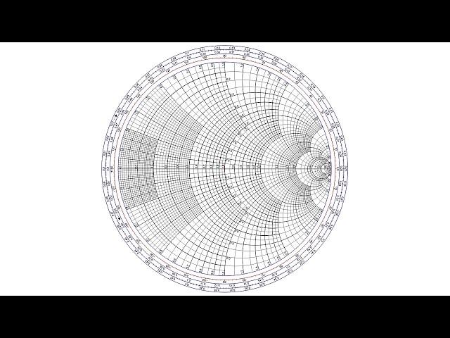
The scariest thing you learn in Electrical Engineering | The Smith Chart
Комментарии:

Reminds me of resonators in a gas engine intake. Trying to get intake pressure pulses to align at a particular engine rpm.
Ответить
I love the rope analogy and would add that waves reflecting due to impedance mismatch is also the same as light moving through the interface of two materials with different indices of refraction.
Ответить
My electromagnetics classes would have been so much easier with explanations like this
Amazing job!

In second year mech. Ive been curious about why complex nunbers was important/used in electrical. Didnt click on the video because of that though. Got that info by accident. Thanks
Ответить
❤
Ответить
i wouldnt exactly call it the scariest thing, it was actually really easy to understand when i learned it a week ago which now i think its weird that this was recommended to me
Ответить
20 kilohertz which is the maximum frequency humans can hear. "Normal Humans".
As a Child I was tested, and verified to hear MUCH higher than that.
I could hear the ultrasonic remote controls (before there were IR LED remotes).
And when they tested our hearing in Junior High, I could hear every tone the machine could put out.
The lady said that "was impossible".
So, they sent a second lady to verify the results. I heard every freq the machine could put out.
I still have "super human" hearing at 55 after a lifetime of working around very loud noise.

Maximum power transfer when source and load impedance match.
Ответить
Ah so this is what was meant by impedance matching, awesome video!
Ответить
Haven't even watched the video I just want it to be known that the thumbnail gave me PTSD
Ответить
Usually antenna analyzers call Z0, which you call the feedline impedance, they call Z0 the system impedance. The center of the Smith chart is the system impedance, usually 50j0. The Smith chart calls this 1j0, which is why you divide by the system impedance, 50 ohms. It's cool to have an antenna analyzer plot a Smith chart of an antenna's feedpoint impedance over a range of frequencies. If the plot is not centered on the chart, you can move it left or right by changing the system impedance. Let's say the plot centers up better with a system impedance of 200 ohms. That means a 200 to 50 ohm balun would give you a better match to the 50 ohm feedline. Of course, if the plot is mostly above or below the center line, the antenna would need some loading capacitance or inductance to bring it closer to resonance. I recommend playing around with the Smith chart plot on an antenna analyzer. Modern antenna analyzers certainly beat the old days when I was sitting under the broadcast tower with an RF bridge plotting the Smith chart by hand.
Ответить
I had an excellent professor for emag. Zach's explanation is as good as you will ever get. I had long since forgotten why the heck I even used the Smith chart, but this was an AWESOME refresher and now I'll never forget it!
Ответить
I don't remember it being taught here in Brazil, I'm a last semester EE student and I don't think I ever heard about it when I studied waves and propagation.
Ответить
Ict
Ответить
applies to steel designs too.. not just radio waves. Ever wonder why the tail frame of a truck is smaller than the front... when in the back that is where people latch hitches to hook up to trailers? it is to stop the wave and send an echo back at it's source..the trailer. That is a simple example with steel.
Ответить
This was by far not the scariest thing we had to learn
Ответить
Laughs in thermodynamics
Ответить
I had forgotten these charts until now.
- and now remembered my CB - AM; at my parents house I pulled an 11metre pipe up a tree and connected the centre conductor; Outer to a ground stake ; the SWR of the antenna was, unmeasurable.
Until then my friend with his half-wave antenna thought he was pretty good - however he was [and still is] on a hilltop - he won.

...i didn't think it was that hard. I used to work with them every day, they were pretty handy.
Ответить
So...what's the scary part?
Ответить
As a mechanical engineer, I’m glad I’m a mechanical engineer.
Ответить
I had a physics student tries engineering moment the other day where i designed and printed a 2GHz stepped impedance low pass filter without knowing a single thing about microwave signal engineering. Needless to say it completely sucked ass and I wish I saw this sooner
Ответить
so this is what that math is for that i learned in school? good to know. too bad im not a fkn electrical engineer...
Ответить
I'm downvoting this nine minute video because the Smith chart is one of the easiest things in microwave engineering. Before computers rendered complex arithmetic trivial, the Smith chart allowed one to easily translate impedances along transmission lines and apply reactances. To the creator: you could have extracted just as much ad revenue with a video on the "genius" of the Smith chart. Or, in case you failed your institution's microwave course, get good.
Ответить
Can we make hifi audio better with this?
Ответить
I'm pretty sure that signals don't travel at the speed of light in a cable, do they?
Ответить
I'm not electrical engineer but I understand it all, very, VERY good explanation.
Ответить
Thanks. Just need to explain now flow chart in RF
Ответить
are we not going to talk about the mathematical error within the first 45 seconds of the video or
Ответить
Does it remind you that current flows in the field not the conductor.
Ответить
Audio frequently is something completely different!!!! 🤷🏻♂️😑😑🤦🏻♂️🤦🏻♂️🤦🏻♂️
Ответить
Very good intro to the Smith charts. We used them a lot at the university for calculations in microstrip circuits.
Ответить
I'm no physicist or electrical engineer, but this is interesting. I want to know where this chart comes from now.
Ответить
Rather than mentioning stub matching they could have simply shown the use of inductors and capacitors in series or shunt configurations to correct the mismatch as an animation on the chart.
Ответить
Hi another engineer that found this explanation better than anything in college. College is such a waste. We need to find a better way to train and educate future engineers
Ответить
As an RF engineer much of product tuning is this very thing (impedance matching). We used metal tabs on microstrip transmission lines, as well as dielectric & ferrite chips.
Ответить
looks like the flower of life to me 🤗
Ответить
Nice video, but it may be misleading. If you have no transmission line between TX and antenna all power will eventually get radiated because energy will simply be reflected again by the TX until everything gets radiated. The TX will suffer from high voltages but it won't dissipate the reflected power as is often found in the literature. Reflected energy was a problem with analog TV transmitters sometimes since it leaded to image ghosting because the antenna was radiating the present and past signals at the same time. This was avoided by totally dissipating the reflected signal, thus lowering global efficiency.
Ответить
到底是什么大脑能想到把两个直尺变成一个圆规
Ответить
Yeah RF Circuit design was the hardest class I took in my undergrad degree. Got an A somehow
Ответить
Learned more about SWR in this 9 minute video than I learned in 7 years as a General Class amateur radio operator.
Ответить
I'm in the wrong room ig
Ответить
Can this also apply to matching an audio amplifier to a loudspeaker with the right impedance rating?
Ответить
I am no way an electrical engineer but you have helped me understand impedance which i have always struggled to understand. Thank you
Ответить
Your rope analogy is a very intuitive way to explain the concept of impedance matching. Great job!
Ответить
How does temperature affect wave length?
Ответить
And now explain how this is scary... 🤷♂
Ответить


![How to Fix SrtTrail.txt Log Error in Windows 10/8/7 - [2024 Tutorial] How to Fix SrtTrail.txt Log Error in Windows 10/8/7 - [2024 Tutorial]](https://invideo.cc/img/upload/TWYyczhOY3h2Tk0.jpg)


![Cara Install SNACK VIDEO di Laptop/PC + CARA CEPAT DAPAT UANG DENGAN SNACK VIDEO [AUTO CLICKER] Cara Install SNACK VIDEO di Laptop/PC + CARA CEPAT DAPAT UANG DENGAN SNACK VIDEO [AUTO CLICKER]](https://invideo.cc/img/upload/WThZaDRwZkUyR1Y.jpg)


