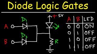
Diode Logic Gates - OR, NOR, AND, & NAND
Комментарии:

I was able to design the 7 logic gates using only diodes, without any transistors
Ответить
Thaaaanks
Ответить
good explanation gates
Ответить
Well explained - but my man.. TH and F do not carry the same sound Both is not pronounced BOF
Ответить
thanks a lot bro!!
Ответить
the first time ive left from a toct video without understanding anything :/
Ответить
yes we have exam tomorrow 😂
Ответить
Where is the OUTPUT node of these gates? With respect to inputs A and B, there must be an usable Output pin to drive, e.g., the base of a transistor.
Ответить
Ah thank you so much I've been searching everywhere for a reasonable explanation and finally ended up here.
Ответить
Great videos. You explain very well. Are you going to add videos on FETs and more? Thank you
Ответить
you are damn genius !!
Ответить
please i have a question, for the And gate why can't current flow from the 5v to led?
Ответить
Awesome job!
Ответить
This is class 12 syllabus in India
Ответить
Amazing video and very clear and detailed explanations. Thank you sir.
Ответить
Cant thank enough! RESPECT ++
Ответить
Wow! That sure wore my brain out trying to develop each circuit BEFORE you showed and explained the right circuit. I still haven't developed the intuitive understanding, but this certainly helped me better see the current flow and voltage differences. I've gone through your videos on circuit analysis and those helped me follow your explanations after the fact. My wife walked in while i was looking at the video and she (Masters in Adult Education) exclaimed "Now THAT'S the right way to teach!", being impressed with the clarity of how you had laid things out. Congratulations and thanks. I had to keep re-watching parts to fully understand, but definitely worth the time. I've watched videos which clearly explained how to use logic gates with switches (esp. ElectroBoom), but this is the first showing how the logic gates themselves can be built.
Ответить
Thank u sooo much...
Ответить
Thank you!
Ответить
This guy knows I'm his biggest fan
Ответить
Great
Ответить
Damn!! This is a great explanation. Cleared all my doubts.
Ответить
Stick to chemistry; your teaching technique for logic functions is worse than poor; it is wrong. By changing how the LED is connected to the input diodes, you are flipping back and forth between active-high and active-low logic conventions without a word of explanation. On and Off have no place in a truth table, which is why 50% of your tables are semantically correct, but logically wrong. If you instead assign 1's and 0' to the outputs, you will see that the NOR and NAND tables are wrong. The problem is the schematics. The schematic for a particular type of gate is what it is, with no regard for what is connected to the output. Your truth tables depend on changing output connections, whereas correct ones do not.
Ответить
Thanks very much for the very simplified explanation,you are a real pro
Ответить
What about all of the other logic gates such as XOR, negative-OR, negative-AND, negative-XOR, etc...Also on the AND-gate towards the end, you said the potential at the point right before the LED was 3.5-V, how is that possible? If the potential is 5-V at A or B and the Diodes drop 0.7-V across each of them , that leaves 4.3-V. Since 4.3 > 3.5, shouldn't that be the potential at that point?
Ответить
Understand nothing
Ответить
why google say there are only two types of diode logic ? one is diode logic OR gate and diode logic AND gate .
Ответить
Wow, this is amazing. Do you have one for Transistor Logic Gates?
Ответить
Diodes connected in parallel would act like which gate???
Kindly explain me.

I’m curious as to how these circuits can be used to derive a +5V trigger or gate signal for use with a modular synth circuit. Where would one tap the signal in order to get a healthy +5V based upon the resulting truth tables? I’m especially interested in the AND circuit.
I built one with 2 NPN xstrs but the resulting output is useless. Building it with diodes and a 5 volt rail seems like a good time.

Brilliant explanation for this topic!
★★★★★

My professor has easier explanation of NAND gate
Dr punit bajπ ( HOD physics dept)

Really great presentation, thanks!
Ответить
A very important question here: How can we make each of the two circuits output ... or in other words, how can I connect these logic circuits to be used in a specific logical operation
Ответить
Need Digital Elctronics please
Ответить
Thanks a lot. ❤️
Ответить
Don't know if you will see this or not, but have you ever considered being a private tutor? I would pay good money for you to teach me this subject (electrical circuits and engineering). Though your videos are very helpful, I still get confused and i'd love to be able to ask you questions in real time.
Ответить
It's only God that will bless you
Thanks so much

the best teacher in the world... he teaches in very easier way...
Ответить
This is useless
Ответить
He must be genius for sure as he explains as simple and easy as possible with all points to make me understood in logic gates operations.
Ответить
What about EXOR and EXNOR?
Ответить
I use these in Minecraft alot.
Ответить

![[Enemy At the Gates] WW2 Snipers - Mosin vs Kar98k - "Pick One" Scenario Brief (Ep.7) [Enemy At the Gates] WW2 Snipers - Mosin vs Kar98k - "Pick One" Scenario Brief (Ep.7)](https://invideo.cc/img/upload/TTdEd1g5SXVhQ2k.jpg)


