Комментарии:

One thing I forgot to mention in the video, but did mention in the article, is the units used in the formulas for calculating the time with the resistors and capacitors:
Time is in Seconds
Resistance is in Ohms
Capacitance is in Farads

merci pour la veeo
Ответить
If the switch was simply a spring that makes very limited contact from the impact of a thrown object, would the extremely limited contact time be enough to charge the capacitor?
Ответить
Can multiple LEDs be used in monostable mode and would that change anything else? For instance, if there are three 3v LEDs in series is the resistor needed from pin 3 if using a 9v battery?
Ответить
Very informative! I've breadboarded lots of 555 projects, mostly audio oscillators. Thank you for this video. I understand this chip much better.
Ответить
Just a FYI... Intel release to First microprocessor the Intel 4004 pretty much the same year as the 555.
Ответить
Wow toll
Ответить
We’ve been using 555 timer chip back in college labs 1998, very useful! Awesome!
Ответить
Oooooooohhh....I feel much smarter now :o Thank you <3
Ответить
Just fantastic ! what do I need to add to have LED flashing like an airplane? (strobe)
Ответить
Is it correct that the 555 predates the microprocessor? It looks like the Intel 4004 came at about the same time.
Ответить
소중한정보를 실제회로를 통해 알려주시니 감사합니다.
영상 만드시느라 수고하셨습니다.😊

My fave chip ever invented & so useful for so many things, you have a fantastic clear way of teaching, the internet needs more folks like you, keep up the fantastic work,
Ответить
The latching switch schematic differs from your circuit configuration. The 100k ohm resistor should go in parallel with the 10k ohm resistor at the 555 pin 3 (not at the LED anode node) per your circuit.
Ответить
This video Explains everything 🙏
Although I would like to know how the time equations were derived.

hola quiero pulsar el botón una ves y que dure 30 segundo encendido y luego que se apague y no encuentro solución ayuda
Ответить
In Thailand 5 is a lucky number as it is pronounced "ha". Instead of texting lol in Thailand they text 555 or ha ha ha. So this is the most jovial IC in existence.
Ответить
Thank you for this clean work. Bravo 👏
Ответить
Thank you so much!
Ответить
🤩🤩🤩
Ответить
A 555 timer should always have a local power supply decoupling capacitor. When the connections to the power supply are long, as they often are with a breadboard, I would use two. One would be an aluminum electrolytic cap of perhaps 10 µF (not critical) and the other would be a 100 nF (0.1 µF) ceramic type. The latter should be on short leads as close as practical to the 555. The electrolytic doesn't need to be quite so close.
The big transistors in the output stage of the bipolar 555 are rather slow. When the output switches, both transistors can be partially ON at the same time. This causes a large "shoot-through" current from the Vcc pin to the ground pin. Without decoupling this current spike can pull Vcc very low, then when the spike ends the inductance of the wires to the power source can cause a big voltage spike. Always use a twisted pair of conductors between your breadboard and power supply if you possibly can. Twisting the conductors keeps them very close together which helps a lot to reduce the effective inductance (the magnetic field in one conductor "cancels" that in the other).

Great video I have one question. I have an LED security light, solar. My question is is only comes on for 30 seconds. I really like it to come on for 2 mins. Any ideas what parts I need to change? I can use a soldering iron, but I'm very basic in talent cheers Graham
Ответить
Does it 555 translate to Jesus like 666 is Satan I don't know I'm not religious great video cheers Graham
Ответить
I wish the jump between "novice" and "can actually make something useful" wasn't so huge, with the only practical way of making any real progress simply being "college".
Ответить
Hello and congratulations for the truly extraordinary video, I wanted to ask you, is it possible to have all 5 LEDs light up at the end of the sequence? and then starts all over again. Hi, I always follow you, you're very good.
Ответить
Thanks for great videos! I have a question, I want to control two 12v 4-wire PWM fans manually, but also with an Arduino, Nano, RPi or other microcontroller and display each fans status to a display. How would you include the microcontroller? Is it also possible to build a custom board to also power the fans, controller, or other add-ons? For example, I have a 110v PRC heater that I would llike to turn on and off to maintain a temperature while the fans are running at variable speeds circulating air.
Do you have a video or similar tutorial?
I’m new on this journey of learning electronics, so thanks again for the knowledge and your patience with the long questions.

TLC 555 can even tolerate 20 V .
Ответить
I love your schematics, as someone new to this stuff I found them very easy to interpret and replicate compared to elsewhere.
Ответить
Thanks
Ответить
What will be the capacitor and resistor values if i need to to generate on and off pulse after 12 hours to turn off my light bulb and the turn on after 12 hours?
Ответить
Very helpful
Ответить
I once built a worble siren with a 556 (dual 555). It was so much fun, because it sounded just like a Italian police siren.
Ответить
Excellent introduction in the 555. Exactly what I needed: 555 in monostable mode in combination with a PIR motion sensor.
Ответить
Very cool & relevant content
Ответить
You are No. 1
Ответить
CAN ONE 220 OHM RESISTOR BE USED IN THE COMMON GROUND SIDE FOR THE LED'S INSTEAD OF 10PCS ?
Ответить
Good video, although the mispronunciation of "battery" over and over did grate after a while (hint, it has three syllables, not just two).
I would argue that the 55 does not actually have ANY "modes", since that implies that the IC is designed to do specific things only. The 555 is really just a set of very well thought out building blocks, which can be combined with external components into a seemingly endless variety of circuits, not just the three mentioned.
As an example, I did a design in the mid '70s where a 555 IC was used to drive the primary winding of a pulse transformer which was in a motor controller circuit to isolate the low voltage control circuit from the high voltage of the TRIAC circuit. I bypassed/disregarded the front-end comparators, and essentially just used the output stage of the IC by driving the Threshold and Trigger pins (they were tied together) from a pulsing logic signal, so that the signal just passed through the comparators and flip-flop and the 555 output was just a slave of the original signal. Why was the 555 used in this way? I used it because it was a simple, inexpensive way to get a fairly high power drive circuit for the pulse transformer (the 555's output circuit can handle quite a lot of current); any other solution would take multiple components (or some other bigger and more expensive IC) and probably cost more than the 555 and also take up more circuit board space. Another reason was that certain failure modes of the high voltage signal could cause the insulation of the pulse transformer to break down, and this would blow up the first solid state component upstream of the transformer. With a driver circuit made from discrete components, more than one part might be in need of replacement in that situation, requiring desoldering and resoldering, but the 555 itself would be the one-stop-shop, and it was quickly and cheaply replaced by unplugging it from its socket.
Another example of how flexible the 555's inherent features can make it; the circuit designer can use the Output pin to discharge the capacitor, and the Discharge pin as the output; this can be handy, as just one example, if you need an open collector output rather than a push-pull output.
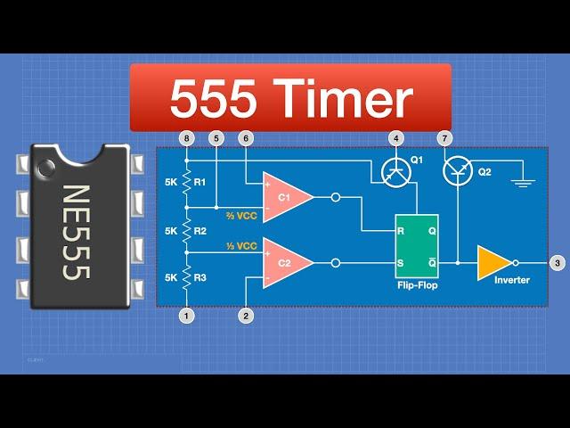
The Control Voltage pin (pin 5) can be used as an input or an output in some creative circuits. It can be used to skew the default comparator voltage thresholds, but it can also be used as a signal input to override the internal resistor divider and apply a changing analog signal directly to the comparators, which is one way to make the 555 into a voltage-controlled oscillator (VCO). Books have been written about the vast number of clever ways the 555's building blocks can be utilized in unusual ways.

Last but not least, the fact that Trigger 2 is connected to pin 4 instead to pin 6 drives me mad. Perhaps I'm missing something. Or many things ;-)
Ответить
In the monostable mode, what happens if I hold the button instead of just pressing it? Will it do the same? (Turn off after x time)
Ответить
Awesome. If I use the monostable configuration proposed in the video example, will my battery be drained while not in use?
Ответить
and if the chip was to go obsolete and no longer made and/or was to go into shortage due to supply line shortage you can make it either from the individual transistors or using op amps and flip flop and transistors.
if the naming did not come from the 3 5k resistors then maybe inspired by the exchange code for the generic phone numbers used by hollywood.
every movie you watch that has a phone number mentioned is usually 555 1212 or 555 1234.
i thought the schmidt trigger was used because it has a very large fanout count where it can directly drive high power loads like an led without the need for a driver transistor.

非常好的老师,非常好的教学,让我学到了很多
Ответить
Absolutely amazing video. Even I, an absolute beginner, can understand things this way. Thanks!
Ответить
Awesome video! I was wondering how do you make the animations and graphics?
Ответить

![Minecraft 1.16 Speedrun in 17:44 [Personal Best] Minecraft 1.16 Speedrun in 17:44 [Personal Best]](https://invideo.cc/img/upload/d1YzXzZiTVBrMEk.jpg)


