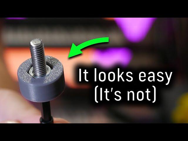
How to 3D Print bores without supports (Fusion 360 Masterclass)
Комментарии:

Interesting. What i figured out for myself is like using a support, not a slicer'support but a part of the model. I place a positive cylinder just by touching the edge of the bore hole, (edge to edge) so the printer bridge, but not into thin air. The nonsupport-support breaks off almost right after i remove the print from the bed. If not, i just break, push it off. Or i don't know maybe negative support would be a better word for it?
Ответить
Slicer issues should be solved in the slicer. If possible. The hexnut issue is solved by adding enough perimeters for the bridging layer. I just add enough, so that the first ring starts on solid ground, as in plastic. The next circle, bounds to its neighbor, just like infill does. The third circle bounds to the second, and so on.
There is is very little droop with this. For M3 nut inserts, that is 2,4mm thick, there is no need to compensate anything. I use this for side inserted nuts, all the time. I do get a layer with 4-5 perimeters though.
I acutually do not understand why the slicer just don't do this by default, because i should. Instead, it draws the perimeter first, and with two few layers, that means printing in mid air. Then it adds the lines that has partial support later on.
Just add a ton of perimeters for the briding layer, and maybe a few more, and watch it print. It is the same mid air bridging prinsiple, as this circurlar thing. Do not remember the name of it.
Also, for bridging, slow the speed WAY down, like 10mm/s, and crank the part fan to 100%. That helps a lot, particularly for PETG.
It is annoying having to do this manually, everytime I print an inserted nut. Particularly one that is slid in form the side, as there is no removing that support, for them prints.

Awesome, thanks for sharing 👍
Ответить
I use a 30 degree rise from the horizontal to avoid support material. Also knowing how much overhang can be done without support is helpful.
Ответить
Anyone know what microphone he's using?
Ответить
ok. and why don't print upside down ? Better connection with table no support.
Ответить
Pause the print and add the nut, then print over the nut.
Ответить
I used to extrude a 1 layer thick material in the hole. So it's just an overhang and usually doesn't need to drill out, the screw can be easily pushed through it.
Ответить
G'day Angus m8.....id love to learn to cad so i can make my own stuff, but the software scares me seriously. Im 49 and have spent since 2018 living a shut in existence living with Anxierty, Deep depression and PTSD plus lower back issues. So most of my chat is done outside the home is done via digital services. It was you guys of the 3d printing community that helped partly by showing me how easy 3d printing was to do in 2020 and so it gave me a hobby and striving when i can to use them i have an ender 3v2 was my first printer and have done some light mods in the last 4 yrs. living with my condition is hard for me and i just get this weird anxierty when someone says " ahh i'll just fix it in cad"... cheers if you read this m8... all good if ya skip it too. cheers from brisbane
Ответить
Why not put the nut in while it’s printing? Before the layer covers it.
Ответить
A couple of alternatives not mentioned in the video. (1) Put a pause in the gcode and drop in a nut (assuming the nut depth is ok). (2) Print a cylinder in the middle of the hex recess, about 0.3mm smaller dia than the screw's bore and use a 1 layer join. Then use this 'slug' as a punch to make a quick, clean break. If the screw hole is blind, put a hole in the middle of the slug to wedge in a scribe point to pull it out)
Ответить
The hardest part of my 3d printing experience was designing parts with machining in mind. I've worked in a CNC shop, programming and machining custom parts, eventually ending up doing a large run of parts for the aerospace industry (F16 and MIG21 upgrades). The design always stuck me as simple and elegant. Once I started to design my 3d printable parts with machining in mind I found out that they were a lot easier to print and in one case, it was an absolute joy going to mass production via injection molding. For people getting into this hobby/profession, I'd recommend reading books on technical drawing, machining basics and industrial design. Their are a Godsent and make learning CAD modelling a pleasant experience!
Ответить
some times i think i know all the tricks already but it turns out that i don’t.
Ответить
Thank you very much for that awesome trick! It made my life as a professional designer and maker of 3D printed parts much easier!
Ответить
"It looks easy (it's not)" - oh no, it is lmao. Me sitting here with a model of a jet turbine with sunk hexagons for nuts that won't be accessible, it surely is that simple. "Can my printer bridge properly the distance it should be able to."
Ответить
If your printer can print 70 degree overhang, you still should design for 45 or less. overhangs quality decreases a lot in angles over 45 and ambient temperature plays a really big whole here, so if you need consistent quality and low fail count, avoid going over 45. If you want a one go print, you can go over and keep watching it while it print
Ответить
I mostly use sacrificial layers. Benefit: it can be easily added to existing models directly in the slicer via adding a small 0.2mm thick disc shape. That would be a cool feature request to do automatic sacrificial layers for holes directly in the slicer
Ответить
The sacrificial bridge gives the very best load distribution between the nut and the printed part. While the alternatives are definitely useful ways to avoid support material on overhangs, I don’t think they’re appropriate for load bearing situations like this. I am sure that where the nut is supported over 50% of its surface area, it will lead to creep (loosening) or stress cracking before a design where the nut is supported over its full surface. Seriously, these are great examples of using bridging, and I thank you for that Angus, but they’re not good examples of how to support a load-bearing insert.
Ответить
for standard sizes and geometries, it can sometimes be as simple as using a wedge of wood, a metal nut, or something similar added to the print before the layers start printing that would need the support.
Ответить
Still trying to understand: So, by not creating an overhang that goes all the way across the center, you get better quality from just doing smaller edges?
BTW, your 3rd attempt (the diamond shaped cutout).. you can just chamfer the hole at 45 degrees. it will round the conical shape, leaving flat surfaces inside at the 6 corners... more support for when you tighten the nut. Better than using your diamond shape removal tool.

Thanks. I've used these approach with my models implemented in OpenSCAD.
Ответить
Nice, very good demo!
Ответить
I cannot remember where but another video says its ok to pause the print before the overhang layer and insert the nut to create a support, this way the nut binds better with the print
Ответить
With adding the bridging as the last step, is it correct that you would need to include an additional offset to the nut-depth parameter to accommodate for the 4-6 additional layers via the bridging?
Ответить
I like the simplicity of the chamfered hole. I think printing an additional chamfered plug with a clearance hole to fill the space would work as well.
Ответить
I don't have any own tricks since I'm sort of new to this. I have seen however something about 90 degrees overhangs using arcs in different sizes. Anything you know something about or have tried yourself?
Ответить
This is amazingly helpful. Thank you!!
Ответить
This technique has one major short coming vs sacrificial bridging, and that is layer height dependence.
Your print now must be printed at the thickness of your bridges or finer else you'll have print failure.
You're also slightly reducing the amount of space available for the embedded nut or bolt head.
It's an awesome technique that I've used many times, but it's not a magic panacea

Genius!
Ответить
Turn the printer side way :)
Ответить
I'm not sure what the big deal is here. I use counter or hex bores/slots in just about every design I make.
If the problem you're trying to deal with is the spaghetti that's going to happen a little bit on bores printed when the bottom of the bore is suspended over the bed, I would humbly suggest that that is not, in fact, a problem. You're going to be jamming a nut in there. Nobody's going to see the bottom of that bore, and you can clean it up a bit after the print is done if it's really that big of a deal.
Anything you might do to solve this problem is mostly just time you could've spent on something else. I say: just run the print with no supports for the bore anyway.

That's an awesome idea! Thank you so much for sharing it, and hats off to its inventor, Nophead.
Ответить
weirdest trick ive used is ysing square holes instead. Has worked for me with m3 holes
Ответить
Awesome! I've used sacrificial bridging for years (learned from you haha) but maybe I'll give the sequential bridging a try! You explained it really well and it could save valuable post-processing time.
Ответить
Thanks for this! Wish I knew about this 6 months ago instead of figuring it out the hard way
Ответить
That process for sequential bridging seems pretty complicated, can Fusion360 not handle that with constraints? I've only really learned Onshape and I'm reasonably sure I could just draw the sketch on the surface that will be bridged, constrain it to the hex nut outline and it would automagically figure it out if I decided to change the dimensions later.
Ответить
Very clever modeling. Thank you for all the great ideas.
Ответить
Thank you for your videos. Alway a view worthy.
A last option you did not mention, maybe because it is a little out of topic, is to insert the nuts during printing. Then the nut will support the bridges.

Thank you for your tips. I really like the sequential bridging idea.
When it is possible, I just simply insert the nut (or any other metallic part) during the printing after I set a pause on the next layer in the slicing.

Hi, I started developing feature scripts for onshape that automates these kind of modifications on 3d models to simplify 3d designing process.
Will you be interested in collaboration to share them with community?
I don't know a better way then share them with 3d printing enthusiasts:)

The sequential pridging works, but I do not think it is an option for larger assemblies with a lot of holes.
I make modular computer case and the amoun of m3 screws and nuts I use make this option impractical. I just chamfer multiple holes with a 30 degree angle at once to print clean cutouts for m3 nuts. Very time efficient and still works well in the printed part.

Interesting video, had you not considered using your 35 or 45 degree step and then print a male insert with the same parameters? This way you have a perfect mate and you could CA join them if necessary... Sequential bridging seems a complicated process to achieve a simple goal...
Ответить
Very well explained 👌
Ответить
In some instances, a support blocker can be used to add an infill pattern that, counterintuitively, supports those floating layers from bores. It's a tried and tested method for me, and I'm printing a piece with such method as I write.
Ответить
How about a custom made cylindrical support?
Ответить
Always a wealth of good information! Thank you for sharing this.
Ответить
Set a pause at the appropriate layer height.
Push the warm nuts into the holes making sure they settle properly.
Resume printing.

After struggling with persistent stringing on my cr6 iv wondered if strategic implementation of stringing might help bridging? Or maybe the strings are too fragile.
The sacrificial bridging idea should be refined to leave to hole open, you can draw tons of straight lines without crossing the space where the hole lives, so a function that automatically does this seems like an obvious add on.


![Low Battery VFX With Sound + Green Screen Overlay [FREE DOWNLOAD] Low Battery VFX With Sound + Green Screen Overlay [FREE DOWNLOAD]](https://invideo.cc/img/upload/Z1RtUFluREhYZEc.jpg)


